SINT
ENGINEERING CONSULTING
AND SOFTWARE


SINT
ENGINEERING CONSULTING
AND SOFTWARE
| Name | Company | Country | Level | Mode | Release Date | Expiration Date |
|---|---|---|---|---|---|---|
| Dawid Lewis | BENTLEY | united states | 2 | Honorary | 1 of December 2021 | 31 of December 2099 |
| Brett Duncan | BJD Consulting Engineers | united kingdom | 1 | Training | 9 of November 2021 | 9 of November 2026 |
| Eduard Shulzhenko | DEHN Germany | germany | 2 | Honorary | 14 of December 2023 | 31 of December 2099 |
| Maddikunta Anwesh Kumar | DEHN Middle East | united arab emirates | 2 | Training | 28 of October 2021 | 28 of October 2026 |
| Jacques Keyser | DEHN South Africa | south africa | 1 | Honorary | 14 of December 2023 | 14 of January 2099 |
| Stefan Nortjie | DEHN South Africa | south africa | 1 | Honorary | 14 of December 2023 | 31 of December 2099 |
| Ivan Grobbelaar | DEHN South Africa | south africa | 2 | Honorary | 14 of December 2022 | 31 of December 2099 |
| Michael Potter | EAST GROUP | united kingdom | 1 | Training | 31 of January 2021 | 31 of January 2026 |
| Ernest Beniger | EDINA GROUP | united kingdom | 1 | Training | 23 of June 2021 | 23 of June 2026 |
| Thomas Scholz | ELIBSYS | germany | 2 | Honorary | 1 of December 2021 | 31 of December 2099 |
| Josè Rodrigo Ayaviri | GERS Ingenieros Consultores | colombia | 1 | Honorary | 29 of July 2022 | 31 of December 2099 |
| Ian Griffiths | GREYMATTERS | united kingdom | 2 | Honorary | 1 of December 2021 | 31 of December 2099 |
| Hugh Wren | GREYMATTERS | united kingdom | 2 | Honorary | 1 of December 2021 | 31 of December 2099 |
| Greg Millett-Clay | GRIDSERVE | united kingdom | 1 | Training | 9 of November 2021 | 9 of November 2026 |
| Declan O'Hara | MAINLINE GROUP | ireland | 1 | Training | 31 of January 2021 | 31 of January 2026 |
| Carl Moller | SAFEARTH Canada | canada | 2 | Honorary | 1 of December 2021 | 31 of December 2099 |
| Mallikarjuna Reddy Gajjala | SIEMENS ENERGY | germany | 1 | Training | 27 of March 2023 | 27 of March 2028 |
| Steve Sommerville | SPE ELECTRICAL | united kingdom | 1 | Training | 31 of January 2021 | 31 of January 2026 |
| Stuart Mc Girr | STUART Mc GIRR | new zealand | 1 | Training | 31 of January 2021 | 31 of January 2026 |
| Katrin Friedl | TECHNISCHE UNIVERSITAT GRAZ | austria | 1 | Training | 31 of January 2021 | 31 of January 2026 |
| Benjamin Jauk | TU GRAZ | austria | 2 | Honorary | 6 of June 2024 | 31 of December 2099 |
| Wagner Costa | WMF CONSULTORIA | brazil | 2 | Honorary | 1 of December 2021 | 31 of December 2099 |
| Rory Bamfield | WSP UK | united kingdom | 1 | Training | 9 of November 2021 | 9 of November 2026 |
| Ryan Jones | WSP UK | united kingdom | 1 | Training | 9 of November 2021 | 9 of November 2026 |
| Mark Horrocks | WSP UK | united kingdom | 1 | Training | 23 of June 2021 | 23 of June 2026 |

LIGHTNING SHIELDING ADVANCED
SHIELD_A can be can be used for the lightning shielding design using the Rolling Sphere method and can be used for the evaluation of the protection against direct lightning strokes of structures of any height and shape.
SHIELD_A is highly appreciated for its power and accuracy.
GENERAL DESCRIPTION
SHIELD_A is a powerful full 3D graphical application for the evaluation of the protection of structures from direct lightning strokes using the Rolling Sphere method. SHIELD is based on analytical model that consider vertical and lateral direct lightning strokes, and is then suitable for structures of any height and shape.
Unlike SHIELD, SHIELD_A can also consider structures with significant protrusions, for instance wind towers, and has been developed mainly for lightning specialists. In essence, SHIELD_A was developed for all applications where SHIELD cannot be used, and is intended to be complementary to SHIELD.

SHIELD can be can be used for the lightning shielding design using the Rolling Sphere or Eriksson methods and can be used for the evaluation of the protection against direct lightning strokes of structures of any height or up to 60 m height in case of relevant protrusions.
SHIELD is highly appreciated for its power, accuracy and flexibility.
{tab GENERAL DESCRIPTION}
SHIELD is a powerful full 3D graphical application for the evaluation of the protection of structures from direct lightning strokes using the Rolling Sphere and the Eriksson methods. SHIELD is based on a numerical model that consider vertical direct lightning strokes, and is then suitable for structures of any height or up to 60 m height in case of relevant protrusions.
The Rolling Sphere Method is considered by many standards (EN, IEEE, NFPA, AS …) and is an universal method for shielding design, and particularly recommended for complex geometry.
Alternative methods like the protection angle or mesh method are suitable for simple-shaped buildings or for buildings where plane surfaces are to be protected.
The Rolling Sphere Method can be applied to the structure to be protected. In such case, SHIELD can identify the parts of the structure exposed to a direct lightning stroke, that are the points where is more effective to install the air termination system.
Then the Rolling Sphere Method can be applied to air termination + down conductor system. In such case SHIELD generates a 3D surface corresponding to the protected volume.
The protected volume is then superposed to the structure to be protected. The parts of the structure to be protected that protrudes over this surface are not protected.
The Rolling Sphere Method has been implemented taking into account a numerical models based on a geometrical scan over a calculation grid, suitable for structures of any height or up to 60 m height in case of relevant protrusions.
The numerical model will consider essentially vertical lightning strokes.
When the Eriksson Method is set, SHIELD generates the collection area of air termination + down conductor system and structure to be protected.
The lightning protection system is effective when collection area of air termination + down conductor system includes collection area of structure to be protected.
The User can modify the lightning protection system and generate again the protected volume or collection areas. This iterative process allows to get an effective shield.
The lightning protection system is effective when collection area of air termination + down conductor system includes collection area of structure to be protected.
The User can modify the lightning protection system and generate again the protected volume or collection areas. This iterative process allows to get an effective shield.
Lightning shielding is an increasing important topics. In many areas the flash density is growing and on the other side the values to be protected (people, buildings, systems …), are also increasing. A good lightning shielding design is the first step for a good lightning protection system installation.
{tab INPUT DATA}
{tab OUTPUT RESULTS}
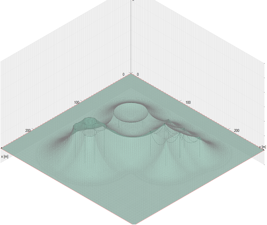
Protected Volume calculated with the Rolling Sphere method
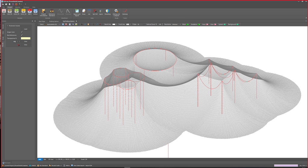
Protected Volume calculated with the Rolling Sphere method (vector graphic)
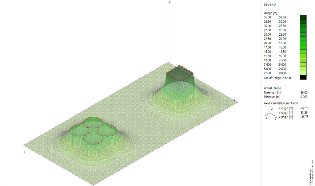
Protected Volume calculated with the Rolling Sphere method
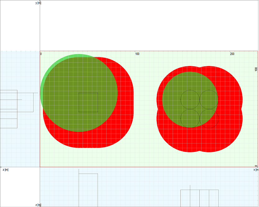
Collection areas calculated with the Eriksson method
{tab MAIN FEATURES}
{/tabs}

NETS can be used for analysis of multi-conductor and multi-phase full meshed networks also in cases of multiple connection to earth (when the sequence components method cannot be applied) and is commonly used for the evaluation of current distribution in fault and steady state conditions in cables and power lines, including the evaluation of current along screens, armors and overhead earth wires.
NETS can be used also for the evaluation of fault current distribution and and is commonly used for the split factor calculation in general conditions.
NETS can be used also for electromagnetic interference analysis of aboveground and underground systems at power frequency, and is commonly used for the evaluation of interference between power lines or cables or railways and pipelines.
NETS is highly appreciated for its power, accuracy and flexibility.
{tab GENERAL DESCRIPTION}
NETS is a computation code for the solution of full meshed multi-conductor and multi-phase underground and/or overhead networks in the frequency domain. The application range is limited to the model accuracy of transformers (up to 1 kHz) cables (up to 1 kHz) and lines (up to 10 kHz).
NETS is based on the phase components method (and then on Kirchhoff laws) and graphs theory for multi-conductor and multi-phase systems. The phase components method is general and overcomes the limits of the classic sequence components method and can be used to represent power systems as multi-conductor networks enabling the consideration of non-symmetrical systems also in presence of multiple grounding circuits. The maximum number of conductors (and so of ports for a single cell side) is 26, so enough to represent most network components (the simulation of 6 cables with core, screen and armour requires 18 conductors).
The network components (sources, ideal voltage generators, ideal current generators, loads, transformers, lines, single core and multicores cables, hybrid links, impedances, switches, faults …) are represented with multi-port cells and the connection between cells is obtained by means of multi-port buses. The grounding systems (substation grids, tower footings …) can be specified in an arbitrary way.
NETS calculates parameters of lines and cables starting on data normally available in commercial data sheet. NETS calculates self and mutual impedances and admittance for all conductors using accurate formulas and taking into account the earth resistivity and permittivity.
NETS calculates parameters of single-phase or three-phase two or three-winding transformers starting on data usually available in commercial data sheet.
NETS includes a converter from the sequence domain to the phase domain. This tool can converts a sequence impedances matrix to a phase impedance matrix.
NETS can be used to solve symmetrical or non-symmetric, balanced or unbalanced transmission and distribution networks in steady state or fault conditions.
In particular, NETS can be used for the calculation of the fault current distribution in power networks and between power circuits and earth.
Moreover, NETS is a powerful tool for the evaluation of current distribution and electromagnetic interference in case of railways corridors.
An accurate knowledge of the fault current distribution is crucial in grounding, mitigation to reduce interference on communication circuits and pipelines, power system protections calibration and coordination, neutral grounding resistor sizing and many others applications.
{tab INPUT DATA}
{tab OUTPUT RESULTS}
{tab MAIN FEATURES}
{/tabs}
Gallery
{gallery}sint/nets{/gallery}
Page 1 of 3